Configured for U.S. facilities
U.S.-market. Application-specific.

Your process.
Your space.
Your cooling system.

Custom heating, cooling, and fan coil systems. Designed around what your process needs—and built to fit where you need them.

For U.S. projects.  Configured around your facility power and approval requirements.
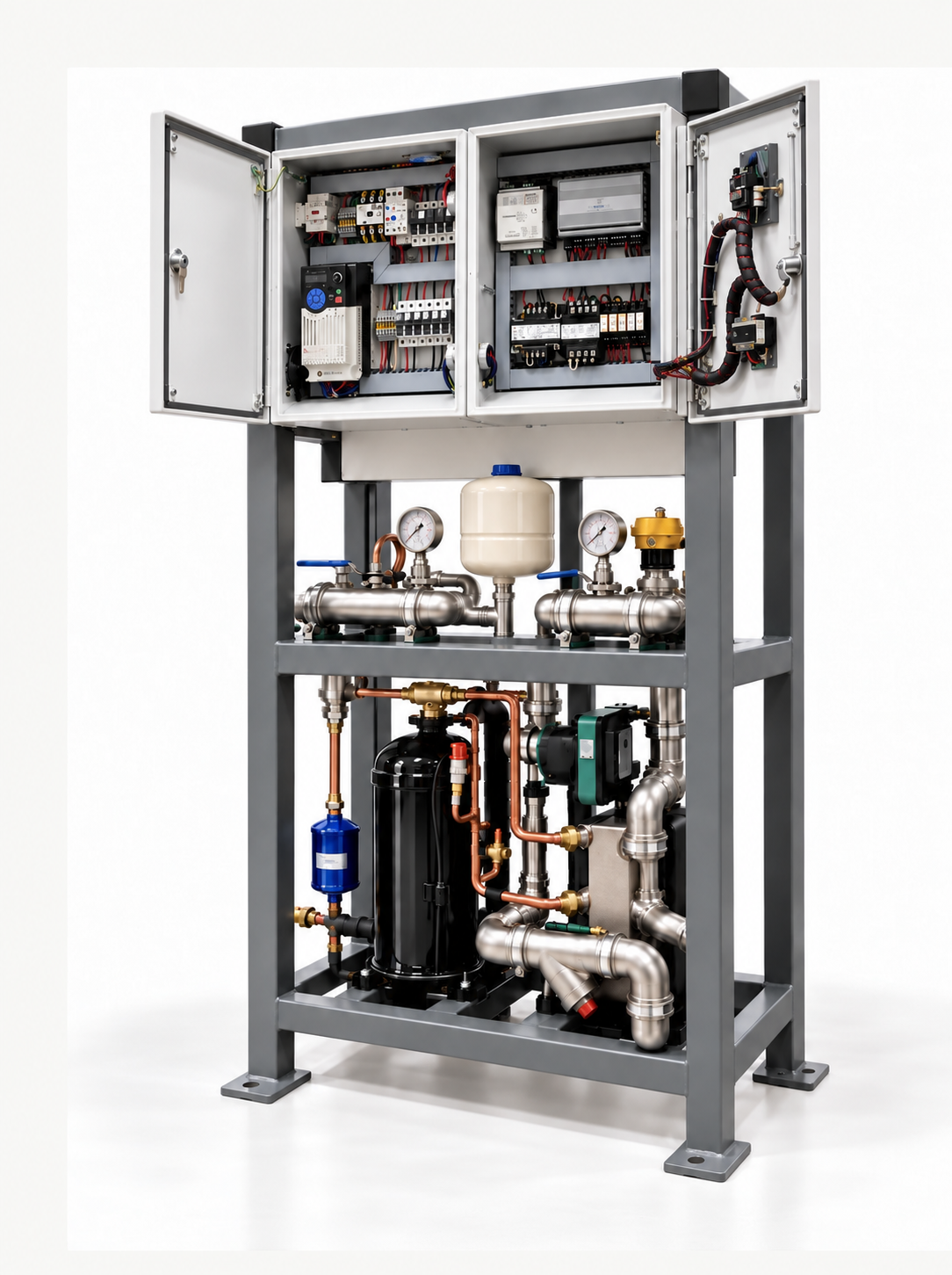
Osprey Chillers open-frame 8-ton R-410A heat pump and chiller
Open-skid hydronic system8-ton heat pump / chiller · R-410A
Osprey open-skid system with electrical control panels and hydronic components visible
Open-panel system viewControls and hydronics shown
Process-specific designCustom footprintsOpen-skid constructionU.S.-market electrical options

Our systems

The right system.
Not just the closest fit.

Heating and cooling equipment should work around your application. Start with your requirements, then build the system around them.

01 / HYDRONIC SYSTEMS

Custom chillers &
heater/chiller systems.

Hydronic units designed around your required capacity, fluid, supply temperature, flow, and operating cycle. Cooling-only or heating-and-cooling configurations, with piping, pumps, and controls selected for the process.

Process coolingHydronic heatingCustom skid layouts
Discuss a hydronic system
02 / AIR-SIDE SYSTEMS

Custom fan
coil units.

Fan coil units designed to match your available space and heating or cooling requirements. Coil selection, airflow, mounting arrangement, connection locations, and service access are considered together—not as afterthoughts.

Heating & coolingSpace-conscious layoutsApplication-matched airflow
Discuss a fan coil unit

Designed per process

The application
comes first.

Your load, your operating conditions, your footprint. We work from those constraints to develop a practical system layout, rather than asking you to adapt your process to a standard box.

Custom ambient design targets−31°Fto+95°F

Designs can be developed for specified environments within this range. Operating limits, capacity, fluid protection, and component selection are confirmed for each project; this is not a universal rating for every unit.

01Your process
Heat load, target temperatures, fluid compatibility, flow, pressure, operating cycle, and control requirements establish the design basis.
02Your available space
Footprint, height, doorways, installation route, connection locations, and maintenance clearances shape the physical layout.
03Your environment
Indoor or outdoor placement, ambient extremes, moisture, and exposure guide frame finish, component protection, and freeze-protection provisions.
04Your operation
Typical U.S. configurations include 208–230 V or 460 V equipment for 480 V service, 3-phase, 60 Hz. Final power supply, controls, SCCR, and approval requirements are confirmed before the build.
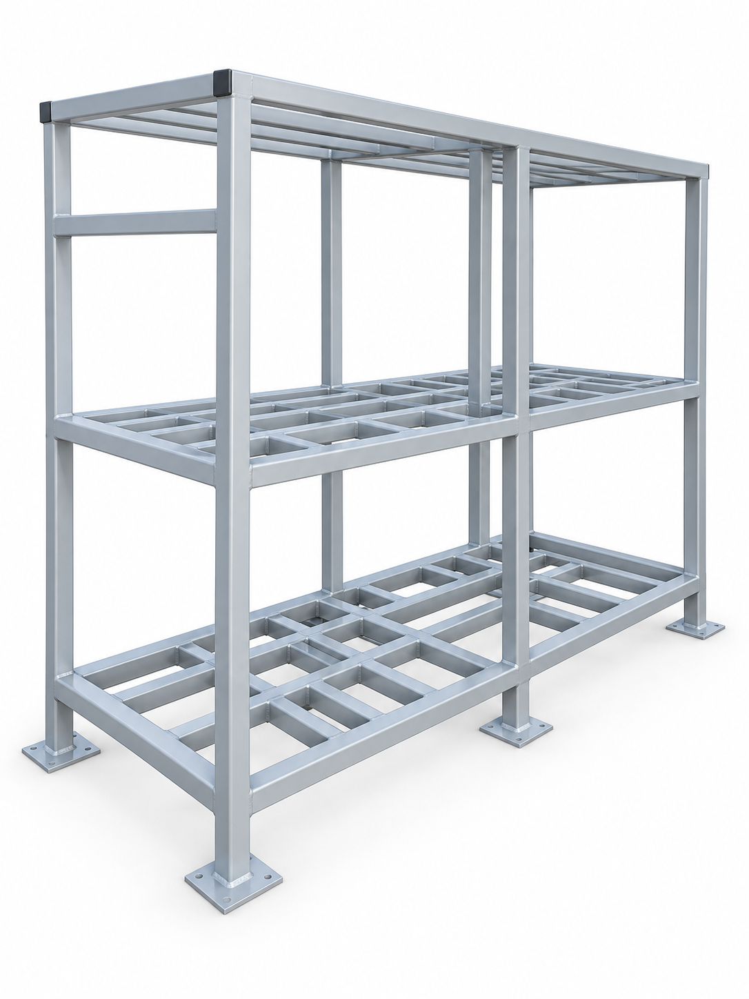
Powder-coated steel frame configured for two 22.5-ton R-410A systems
Powder-coated steel frame shown2 × 22.5-ton R-410A system frame
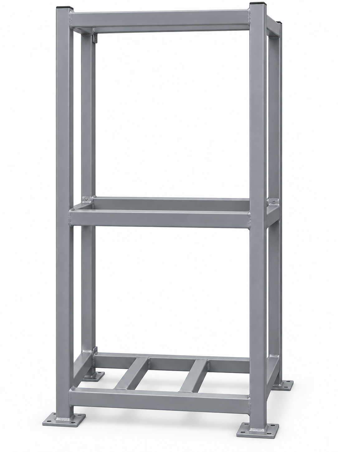
Painted-steel frame for an 8-ton R-410A heat pump and chiller
Painted steel frame shown8-ton heat pump / chiller · R-410A
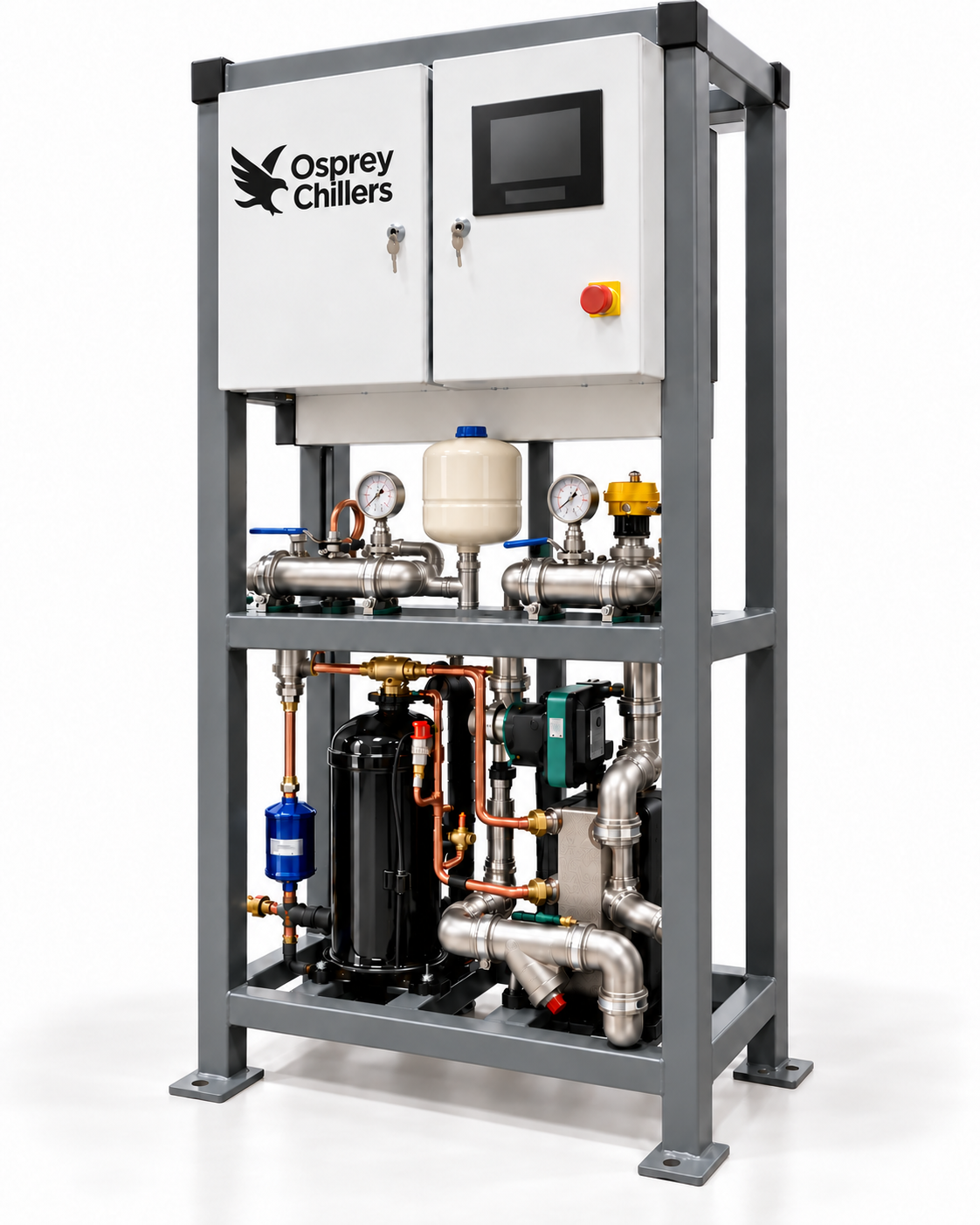
Open-skid frame concept, with access around the components
Open by designIllustrative frame concept

Open-skid construction

Built on a frame.
Not hidden in a box.

An open-skid layout makes the arrangement of piping, pumps, heat exchangers, and controls part of the design. Components remain accessible for installation, inspection, and service, with space allocated where it matters.

Frame material and finish are selected for the setting. Guards, electrical enclosures, and weather protection are specified where the application requires them.

  • Powder-coated steelFinished to suit the application
  • Painted steelProject-specific coating and colour
  • Stainless steelFor specified environmental needs

U.S. project configuration

Built around your facility.
Built for your process.

Work directly with Osprey Chillers to define the application, layout, U.S. electrical configuration, documentation, and project-specific approval path for your facility.

U.S.-focused sourcing

U.S.-origin component options.

For U.S. projects, we can evaluate and prioritize U.S.-origin or domestically stocked compressors, pumps, controls, electrical components, and service parts where project requirements and availability allow. This can simplify procurement, improve replacement-parts availability, and may reduce exposure to cross-border tariffs and delays.

Final component sourcing, country of origin, availability, and tariff treatment are confirmed for each project.

Start a conversation
Development concept

ThermaVoltHx / Four-circuit thermal conversion

Recover the heat.
Generate power. Reuse heat.

A traditional chiller consumes electricity to move heat, then rejects that heat outdoors. ThermaVoltHx is being developed as a four-circuit system: an R-1224yd(Z) power circuit, a separate pumped R-1224yd(Z) heat-output circuit, a dedicated POE oil circuit, and a process-fluid circuit through HX1. The heat-output circuit can serve a fan coil or an optional hot-water recovery exchanger. R-1224yd(Z) was selected for its low environmental impact and very low global-warming potential. Generated power can offset site demand and, through an approved grid-tied inverter and utility interconnection, may be exported and sold back to the grid where local programs permit.

The operating concept

  1. 01

    Process-fluid circuit

    The 25–30% propylene-glycol process fluid passes through HX1, transferring process heat into the power circuit.

  2. 02

    HX1 captures heat

    In HX1, R-1224yd(Z) absorbs heat from the glycol circuit and leaves toward the booster compressor.

  3. 03

    Booster compression

    The booster screw compressor raises the refrigerant pressure and temperature before it enters the expander.

  4. 04

    Expander + PMG

    A reverse screw compressor acts as the expander and drives a permanent-magnet generator as the refrigerant expands.

  5. 05

    HX2 transfers heat

    HX2 condenses the power-circuit refrigerant while transferring useful heat into the separate R-1224yd(Z) circuit.

  6. 06

    EEV closes the power loop

    The electronic expansion valve meters the condensed refrigerant, reduces its pressure, and returns it to HX1.

  7. 07

    Pumped heat-output circuit

    A pump circulates the second R-1224yd(Z) circuit from HX2 through a fan coil or optional hot-water recovery exchanger and back to HX2.

  8. 08

    Dedicated oil circuit

    A separate POE oil circuit with reservoir, pumps, filtration, pressure control, and oil cooling supports the booster compressor and expander.

Power circuitHX1 → booster compressor → expander / PMG → HX2 → EEV → HX1
Heat-output circuitHX2 → fan coil / hot-water recovery → pump → HX2
Process-fluid circuitProcess return → HX1 → cooled process supply
Oil circuitReservoir → pumps / conditioning → booster + expander → reservoir
Energy sourceNormally rejected chiller heat
Electrical outputReverse screw expander + PMG + grid-tied inverter
System benefitLower net demand + useful heat recovery
Grid connectionSite-load offset + approved power export

Concept specifications

Architecture
Four coordinated circuits: power refrigerant, heat-output refrigerant, POE oil, and process fluid
Cooling capacity target
Approx. 488,000 BTU/h
Equivalent cooling capacity
Approx. 40.7 refrigeration tons / 143.0 kW thermal
Preliminary process flow
70 GPM — 25–30% propylene-glycol circuit
Preliminary process temperatures
45°F entering / 32°F leaving (13°F drop)
Working refrigerant
R-1224yd(Z) in both refrigerant circuits
Refrigerant environmental profile
Very low GWP (~1) · A1 safety classification
Heat-output circuit flow
35 GPM — pumped R-1224yd(Z) circuit
Dedicated oil-circuit flow
Approx. 1.5–2.5 GPM — POE oil
Concept model
ThermaVoltHx-30
U.S. electrical service
120/208 V, 3-phase or 277/480 V, 3-phase · 60 Hz
HX-30 auxiliary draw
12.2 kW
HX-30 generation target
30 kW
Optional hot-water recovery target
Approx. 388,000 BTU/h useful heat output
Recovered energy source
Normally rejected chiller heat
Intended result
Electricity generation + useful heat recovery + reduced net demand
Generation equipment
Reverse screw expander, PMG and grid-tied inverter
Grid interface
Site-load offset with potential utility-approved power export
Control concept
Local fast loops + supervisory web controls
Protection concept
Pressure, temperature, isolation and fail-safe interlocks

ThermaVoltHx is a development-stage concept. The approximate 488,000 BTU/h process-cooling and 388,000 BTU/h optional hot-water-recovery figures are preliminary design targets from the final concept drawing, not tested ratings. Actual performance depends on fluid properties, flow, temperatures, component selection, and operating conditions. Cooling capacity and recovered heat are thermal duties, not electrical output. All four circuits, R-1224yd(Z) selection, ratings, electrical interface, grid interconnection, approvals, net power reduction, and overall performance must be confirmed through prototype testing and project-specific validation. Cooling, heat-recovery, and generation targets are not guaranteed commercial ratings; power export depends on the inverter, local utility rules, an approved interconnection agreement, and any applicable metering or export program.

Let’s discuss the details

Tell us what
you need to cool.
Or heat.

Have a defined specification or an early-stage concept? Start with your process, available space, and operating conditions.

Call905-818-5987Email[email protected]
Find us1442 Osprey Drive, Unit 2
Ancaster, Ontario L9G 4V5
Canada
View directions

A good place to start.

Send a short project brief directly to our team.

Your project details will be sent to Osprey Chillers through our secure form service. We will reply to the email address you provide.